EAP HOST EMULATOR 使用指南
1. 應用程式概述
1.1 什麼是 EAP HOST EMULATOR
EAP HOST EMULATOR 是一款專為半導體製造業設計的 SECS/GEM (Semiconductor Equipment Communications Standard / Generic Equipment Model,半導體設備通訊標準/通用設備模型) 協定模擬器。本應用程式使用 HSMS (High-Speed Message Service,高速訊息服務) 協定進行連線與訊息交換,模擬主機設備 (Host) 與半導體製造設備之間的通訊。
1.2 主要功能特色
本應用程式提供以下核心功能:
- 彈性的事件驅動系統: 透過 Parameter.json 設定檔定義各種設備狀態事件與屬性更新邏輯,支援條件判斷與值對應轉換
- 完整的 SECS 訊息管理: 內建 SML (SECS Message Language) 編輯器,支援訊息的建立、編輯、儲存與傳送
- 參數化系統設定: 可彈性設定連線參數、逾時設定、設備狀態等系統參數
- 視覺化工作流程管理: 提供 WorkCard 與 MaterialCard 的視覺化管理介面
- 智能驗證機制: 支援半導體標準製程流程,包括 Carrier ID 驗證與 Slot Mapping 驗證
- 流程自動化: 整合 Verify Flow、Job Flow 與 Auto Flow 自動化流程
- 結果比對分析: 提供 Process Result 的預期值比對與分析功能
詳細操作示範請參考:
2. 頁面功能介紹
2.1 Setting 設定頁面
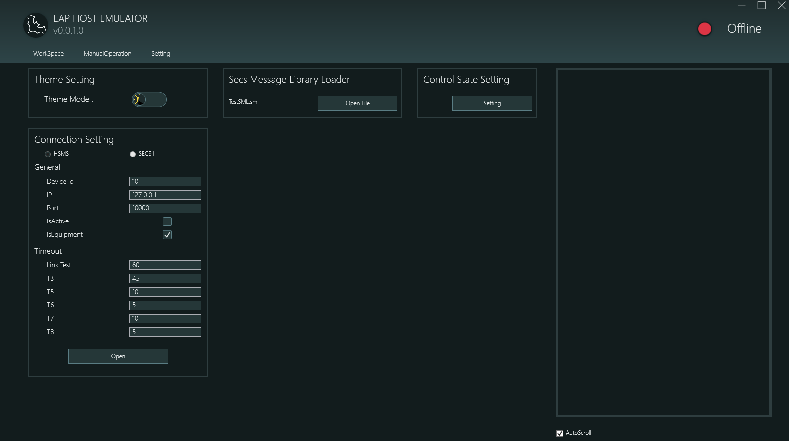
設定頁面提供應用程式的核心設定功能,包含以下四大區塊:
2.1.1 Theme Setting 主題設定
- 功能: 切換應用程式顯示主題
- 選項:
- Light Mode 淺色模式
- Dark Mode 深色模式
- 示範:
2.1.2 Connection Setting 連線設定
本區塊用於設定 HSMS 協定的連線參數:
Protocol Selection 協定選擇
- HSMS (High-Speed Message Service 高速訊息服務)
- SECS1 (Serial Equipment Communication Standard 1 序列設備通訊標準 1)
General Settings 一般設定
- Device Id: 設備識別碼,用於 HSMS 通訊時識別本機
- IP: 目標設備的 IP 位址 (範例: 127.0.0.1 表示本機測試)
- Port: 通訊埠號 (預設: 10000)
- IsActive: 主動/被動連線模式
- 勾選: 主動模式 (Active) - 本機主動發起連線
- 不勾選: 被動模式 (Passive) - 等待遠端連線
- IsEquipment: 設備角色設定
- 勾選: 模擬設備端 (Equipment)
- 不勾選: 模擬主機端 (Host)
Timeout Settings 逾時設定
- Link Test: 連線測試訊息的發送間隔時間 (秒),用於確認連線狀態
- T3: Reply Timeout 回覆逾時 - 等待回覆訊息的逾時時間 (秒)
- T5: Connect Separation Timeout 連線分離逾時 (秒)
- T6: Control Transaction Timeout 控制交易逾時 (秒)
- T7: Not Selected Timeout 未選擇逾時 (秒)
- T8: Network Intercharacter Timeout 網路字元間隔逾時 (秒)
Operation Buttons 操作按鈕
- Open: 建立連線 (連線後按鈕變更為 "Close")
- Close: 中斷連線
連線成功後,應用程式右上角的狀態指示燈會從紅色 (Offline 離線) 變為綠色 (Online 線上)。
示範:
2.1.3 Secs Message Library Loader SECS 訊息庫載入器
- 功能: 載入預先定義好的 SECS 訊息範本檔案 (.sml 格式)
- 使用方式:
- 點擊 "Open File" 按鈕
- 選擇 .sml 檔案
- 載入後的訊息會顯示在 ManualOperation 頁面的訊息清單中
- 檔案格式: 支援標準 SML (SECS Message Language) 格式
- Auto-Load 自動載入: 應用程式會記憶上次開啟的 SML 檔案,下次啟動時自動載入
示範:
2.1.4 Control State Setting 控制狀態設定
- 功能: 設定與調整系統控制狀態的參數
- 使用方式: 點擊 "Setting" 按鈕開啟參數設定視窗
- Configuration Items 設定項目: 包含 SystemState 相關的 ControlState 等參數
- Application Scenario 應用場景: 用於模擬設備在不同控制狀態下的行為
示範:
2.2 ManualOperation 手動操作頁面
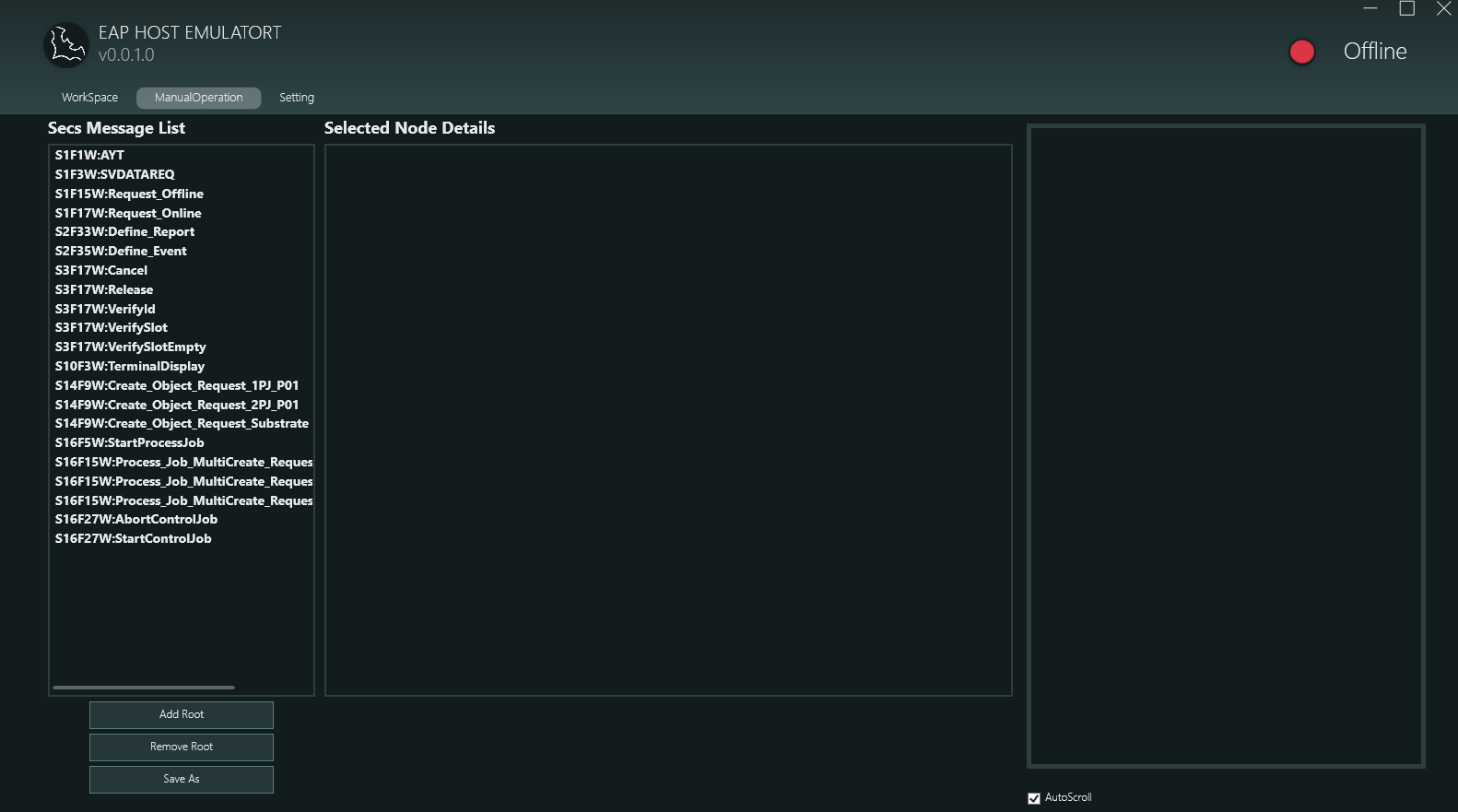
手動操作頁面是 SECS 訊息的編輯與傳送中心,主要包含以下功能:
2.2.1 Secs Message List SECS 訊息清單
左側面板顯示已載入的 SECS 訊息清單:
Message Naming Format 訊息命名格式
- 格式:
SxFy[W]:訊息描述 - 範例:
S1F1W:AYT- Stream 1, Function 1, 有等待回覆 (W-Bit), 訊息為 Are You ThereS1F3W:SVDATAREQ- Stream 1, Function 3, 有等待回覆, 訊息為 Status Variable Data RequestS2F33W:Define_Report- Stream 2, Function 33, 有等待回覆, 訊息為 Define ReportS3F17W:Verify Slot- Stream 3, Function 17, 有等待回覆, 訊息為 Verify Slot
Message Categories 訊息分類
從螢幕截圖可見支援多種 SECS 訊息類型:
- S1Fx: 設備狀態與控制相關訊息
- S2Fx: 設備常數與報告定義
- S3Fx: 物料傳輸與驗證
- S14Fx: 物件服務 (Object Services)
- S16Fx: 流程管理 (Process Job, Control Job)
Operations 操作功能
- Double-Click to Send 雙擊傳送: 雙擊清單中的任一訊息即可立即傳送
- View Structure 查看結構: 單擊訊息可在右側 "Selected Node Details" 面板查看訊息的詳細結構
示範:
2.2.2 Selected Node Details 選取節點詳情
右側面板以階層式方式顯示選中訊息的完整樹狀結構,呈現 SECS 訊息的所有元素。
2.2.3 SML Editor SML 編輯器
本頁面整合了完整的 SECS 訊息編輯功能:
Supported Data Types 支援的資料型態
- LIST: 清單容器,可包含其他元素
- BINARY (B): 二進位資料
- BOOLEAN: 布林值 (0x00 或 0x01)
- ASCII (A): ASCII 字串 (7-bit 字元)
- JIS8: JIS 8-bit 編碼字串 (日文)
- Integer Types 整數型態: I1 (1 byte), I2 (2 byte), I4 (4 byte), I8 (8 byte) 有號整數
- Floating-Point Types 浮點數型態: F4 (單精度), F8 (雙精度)
- Unsigned Integer Types 無號整數型態: U1, U2, U4, U8
Editing Functions 編輯功能
- Add Root: 新增根節點 (訊息)
- Remove Root: 移除選中的根節點
- Add Child: 在清單節點下新增子元素
- Remove: 移除選中的節點
- Save: 將編輯好的訊息存成 .sml 檔案
Editing Workflow 編輯流程
- 建立根節點,命名格式為
SxFy[W]:描述 - 在根節點下新增 LIST 或資料型態節點
- 在 LIST 節點下可繼續新增巢狀結構
- 輸入各節點的值
- 雙擊傳送或儲存為檔案
Template Variable System 範本變數系統
SML 編輯器支援 ASCII 欄位的動態變數替換與型別轉換功能:
Variable Substitution Format 變數替換格式: {{屬性名稱}}
- 將範本替換為實際的 ViewModel 屬性值
- 屬性名稱不區分大小寫
{{CarrierID}}→ 替換為 CarrierID,預設保持 ASCII 型別{{PortNo}}:U1→ 替換為 PortNo 數量,轉換為無號位元組
Supported Type Cast Names 支援的型別轉換名稱 (不區分大小寫):
- 整數型別:
I1,I2,I4,I8,INT8,INT16,INT32,INT64 - 無號整數:
U1,U2,U4,U8,UINT8,UINT16,UINT32,UINT64 - 浮點數:
F4,F8,FLOAT,DOUBLE - 其他:
BINARY/B,BOOLEAN/BOOL,ASCII/A,JIS8
示範:
2.3 WorkSpace 工作區頁面
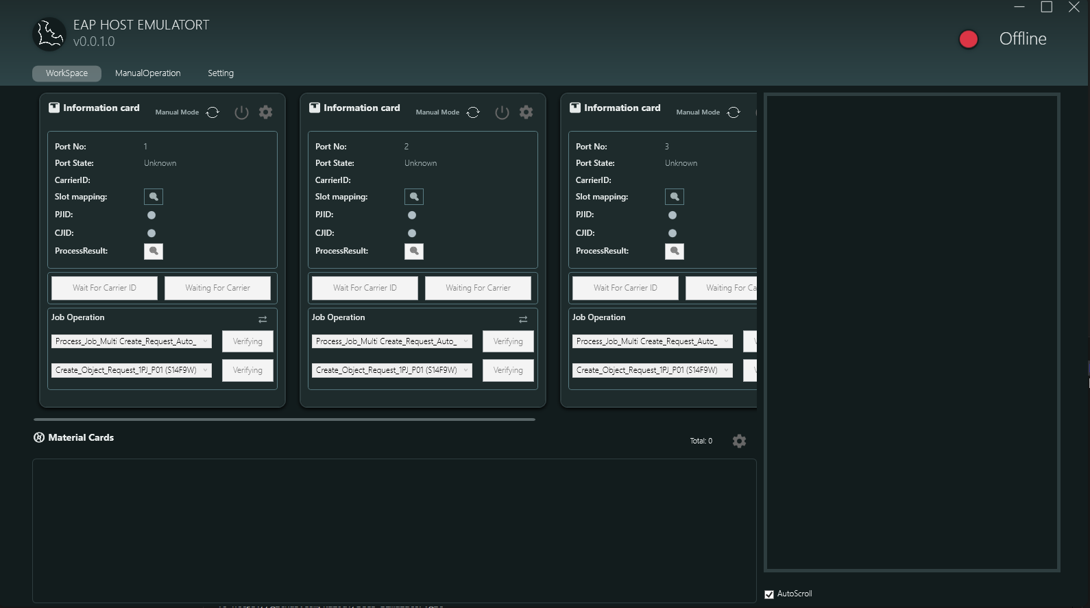
工作區頁面是半導體製程流程的核心管理介面,主要包含以下功能模組:
2.3.1 Information Card Area 資訊卡區域
上方區域顯示多個 Information Card (最多 4 個,對應 Port 1-4),每個卡片代表一個工作端口:
Card Information Display 卡片資訊顯示
- Port No: 端口編號 (1, 2, 3, 4)
- Port State: 端口狀態 (Unknown, LDRQ, LDCM, UDRQ, UDCM, LING, UING)
- CarrierID: 載具識別碼
- Slot mapping: 槽位對應視窗按鈕 (點擊可開啟視覺化槽位視窗)
- PJID (Process Job ID): 製程工作識別碼
- CJID (Control Job ID): 控制工作識別碼
- ProcessResult: 製程結果狀態
Card Function Buttons 卡片功能按鈕
- Manual Mode: 切換自動/手動模式
- Settings Button: 開啟參數設定視窗
- Power Button: 啟動/停止該端口的運作
- Slot Icon: 開啟 Slot Mapping Visual Window
Job Operation Area 工作操作區
每個 Information Card 下方顯示兩個主要操作項目:
- Process_Job_Multi Create_Request_Auto_...: 自動建立多個 Process Job 的請求,顯示 "Verifying" 狀態
- Create_Object_Request_1PJ_P01 (S14F9W): 建立物件請求,指定為 1 個 Process Job,端口 P01
2.3.2 Slot Mapping Visual Window 槽位視覺化視窗
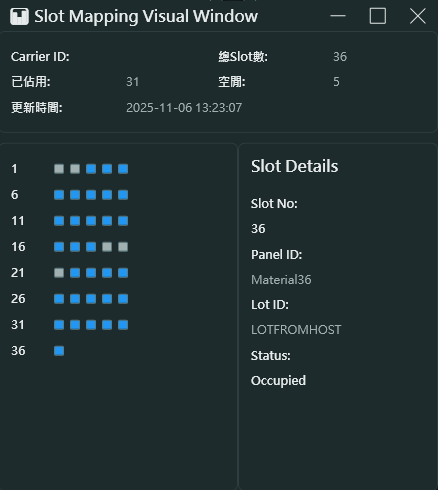
Window Information 視窗資訊
- Carrier ID: 顯示載具識別碼 (範例: Cassette1)
- Total Slots: 顯示總槽位數量 (範例: 36)
- Update Time: 最後更新時間戳記 (範例: 2025-11-06 13:23:07)
- Occupied Count: 目前已佔用的槽位數量 (範例: 5)
Slot Status Display 槽位狀態顯示
- 左側顯示槽位編號 (1, 6, 11, 16, 21, 26, 31, 36)
- 右側以圖形化方式顯示每個槽位的佔用狀態:
- Gray squares 灰色方塊: 空槽位 (Empty)
- Blue squares 藍色方塊: 已佔用槽位 (Occupied)
- 每行顯示 5 個槽位,便於視覺化管理
Slot Details 槽位詳情
點擊任一槽位可在右側查看詳細資訊:
- Slot No: 槽位編號 (範例: 36)
- Panel ID: 面板識別碼 (範例: Material36)
- Lot ID: 批次識別碼 (範例: LOTFROMHOST)
- Status: 槽位狀態 (Occupied, Empty)
Application Scenarios 應用場景
- 載具 (Carrier) 到達時驗證槽位狀態
- 追蹤每個槽位的面板 (Panel) 配置
- 確認批次 (Lot) 的完整性
2.3.3 Verify Flow 驗證流程
驗證流程是半導體製程中的關鍵步驟,用於確認載具與物料資訊的正確性:
Main Verification Items 主要驗證項目
- Carrier ID Verify 載具識別碼驗證
- 驗證載具識別碼是否與系統記錄相符
- Event ID: 262 (CarrierIDVerify)
- Slot Verify 槽位驗證
- 驗證槽位配置是否正確
- 檢查每個槽位的佔用狀態
- Event ID: 301 (SlotVerify)
Verification Process 驗證流程
- 載具到達端口
- 系統讀取 Carrier ID
- 執行 Carrier ID 驗證
- 讀取 Slot Mapping
- 執行槽位驗證
- 驗證通過後更新 Information Card 資訊
Required SML Message Names 必要的 SML 訊息名稱
系統會在載入的 SML 檔案中搜尋特定的訊息名稱。訊息名稱必須符合以下格式 (不區分大小寫):
- Carrier ID 驗證:
S3F17W:VerifyId - Slot 驗證:
S3F17W:VerifySlot - 載具取消:
S3F17W:Cancel - 載具釋放:
S3F17W:Release
示範:
2.3.4 Job Flow 工作流程
Job Flow 管理半導體製程中的工作排程與執行:
Process Job 製程工作
- Events 事件:
- 501 (ProcessJobStart): 製程工作開始
- 502 (ProcessJobEnd): 製程工作結束
- States 狀態: Queued → Setting_up → Waiting_for_Start → Processing → Normal_End
- Property Updates 屬性更新: PJID (Process Job ID), PJState (Process Job State)
Control Job 控制工作
- Events 事件:
- 601 (ControlJobStart): 控制工作開始
- 602 (ControlJobEnd): 控制工作結束
- 604 (ControlJobAbnormalEnd): 控制工作異常結束
- States 狀態: Queued → Selected → Waiting_for_Start → Executing → Normal_End
- Property Updates 屬性更新: CJID (Control Job ID), CJState (Control Job State)
Required SML Message Names 必要的 SML 訊息名稱
系統會在載入的 SML 檔案中搜尋特定的訊息名稱。訊息名稱必須符合以下格式 (不區分大小寫):
Process Job 相關訊息:
- 建立 Process Job: 任何以
S16F15W開頭的訊息 (例如:S16F15W:CreatePJ,S16F15W:ProcessJob_Create) - 啟動 Process Job:
S16F5W:StartProcessJob
Control Job 相關訊息:
- 建立 Control Job: 任何以
S14F9W開頭的訊息 (例如:S14F9W:CreateCJ,S14F9W:Create_Object_Request) - 啟動 Control Job:
S16F27W:StartControlJob - 中止 Control Job:
S16F27W:AbortControlJob
其他訊息:
- 終端顯示:
S10F3W:TerminalDisplay(用於在終端顯示訊息)
示範:
2.3.5 Auto Flow 自動流程
Auto Flow 整合了驗證、工作建立與執行等完整製程步驟:
Automation Flow Steps 自動化流程步驟
- 載具到達觸發 Port State Change
- 自動執行 Carrier ID 與 Slot 驗證
- 根據參數自動建立 Process Job 與 Control Job
- 自動開始工作執行
- 完成後自動卸載並產生 Process Result
Flow Monitoring 流程監控
- 每個步驟會在 Job Operation 區域即時更新
- 顯示當前執行狀態 (Verifying, Processing, Completed)
- 可隨時切換手動模式介入控制
示範:
2.3.6 Result Viewer 結果檢視器
處理完成後,點擊 ProcessResult 可開啟 Process Result Detail 視窗,包含三個分頁:
Comparison Tab 比對分頁
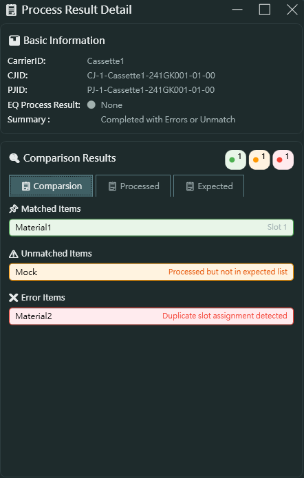
- Basic Information 基本資訊
- CarrierID: 載具識別碼
- CJID: 控制工作 ID
- PJID: 製程工作 ID
- EQ Process Result: 設備製程結果
- Summary: 結果摘要 (Completed with Errors or Unmatch)
- Comparison Results 比對結果
- 顯示三個統計指標 (綠色/橘色/紅色圓圈)
- Matched Items 符合項目: 綠色,顯示符合預期的物料清單
- Unmatched Items 不符合項目: 橘色,顯示處理了但不在預期清單中的物料
- Error Items 錯誤項目: 紅色,顯示發生錯誤的物料
從範例螢幕截圖可見:
- Material1 符合預期 (在 slot 1)
- Mock 不在預期清單中 (Processed but not in expected list)
- Material2 發生錯誤 (Duplicate slot assignment detected)
Processed Tab 已處理分頁
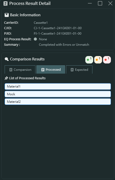
- List of Processed Results 已處理結果清單
- 顯示實際處理的所有物料清單
- 範例: Material1, Mock, Material2
Expected Tab 預期分頁
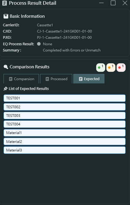
- List of Expected Results 預期結果清單
- 顯示應該要處理的物料清單
- 可包含測試資料 (TEST001, TEST002, TEST003, TEST004)
- 實際物料 (Material1, Material2, Material3)
- 用於比對實際處理結果與預期結果的差異
Result Status Mapping 結果狀態對應
- Normal_OK (1): 正常完成
- Duplicated_Panel_ID (2): 重複的面板 ID
- Abnormal_MatchNG_Bypass (3): 比對失敗但略過
- Read_NG_BackFOUP (4): 讀取失敗退回
- Abnormal_MatchNG_BackFOUP (5): 比對失敗退回
- Abnormal_Panel_Insufficient (6): 面板數量不足
- Abnormal_FOUP_Cancel (7): 載具取消
- Abnormal_Job_End (8): 工作異常結束
- 其他狀態...
2.3.7 Material Cards Area 物料卡區域
下方區域顯示所有物料卡片的狀態:
Material Card Creation and Deletion 物料卡建立與刪除
- Creation Event 建立事件 (763 - MaterialCreated): 當物料建立時自動產生卡片
- Completion Event 完成事件 (704 - MaterialDeleted): 當物料處理完成時移除卡片
- Total Counter 總計數器: 顯示目前系統中的物料卡片總數
Material Card Information 物料卡資訊
- MaterialID: 物料識別碼
- AssociatedPortNo: 關聯的端口編號
- AssociatedPortSlot: 關聯的端口槽位
3. Parameter.json 參數系統
本應用程式的核心特色在於其事件驅動架構。透過 Parameter.json,您可以彈性定義:
3.1 System Events 系統事件
定義在 System.SystemState 區段,例如:
- EventID 1 - ControlStateChanged: 控制狀態變更事件
- 更新 ControlState 屬性
- 支援值對應: 0→Offline, 3→OnlineLocal, 4→OnlineRemote
3.2 WorkCard Events 工作卡事件
定義在 WorkSpace.WorkCards 區段,每個 WorkCardID 可設定多種事件:
- 201 - PortStateChanged
- 262 - CarrierIDVerify
- 301 - SlotVerify
- 501/502 - ProcessJob Start/End
- 601/602 - ControlJob Start/End
- 603 - UnloadCarrierData
- 604 - ControlJobAbnormalEnd
3.3 MaterialCard Events 物料卡事件
定義在 WorkSpace.MaterialCards 區段:
- CardCreated → Event 763 (MaterialCreated)
- CardCompleted → Event 704 (MaterialDeleted)
3.4 Property Update Mechanism 屬性更新機制
每個事件可定義多個 UpdateProperty 項目:
- ValueName: 屬性名稱
- ValuePath: 從 SECS 訊息中提取值的路徑 (陣列索引)
- ValueMode: 值模式
- Direct: 直接使用值
- Mapped: 透過 ValueMappings 對應轉換
- Condition: 條件判斷邏輯 (支援 ==, !=, in, &&, || 等運算子)
4. 應用場景
4.1 Development and Testing 開發與測試
- 在無實體設備的環境下進行 SECS/GEM 通訊協定開發
- 測試主機 (Host) 與設備 (Equipment) 間的訊息交換
- 驗證自訂的 SECS 訊息格式
4.2 System Integration 系統整合
- 模擬半導體製程設備的行為
- 驗證 MES (Manufacturing Execution System 製造執行系統) 與設備的整合
- 測試異常情況的處理邏輯
4.3 Education and Training 教育訓練
- 學習 SECS/GEM 通訊協定標準
- 理解半導體製造流程中的設備通訊
- 訓練操作人員熟悉設備狀態與訊息流程
5. 技術規格
- Development Framework 開發框架: WPF (.NET Framework 4.8)
- Architecture Pattern 架構模式: MVVM (Model-View-ViewModel)
- Communication Protocol 通訊協定: HSMS / SECS1
- Message Format 訊息格式: SML (SECS Message Language)
- Configuration Format 設定格式: JSON (Parameter.json)
- Logging System 日誌系統: log4net
6. 快速開始
- 啟動應用程式
- 切換至 Setting 頁面,設定連線參數並點擊 Open 建立連線
- 載入 SML 訊息庫檔案 (*.sml)
- 切換至 ManualOperation 頁面,雙擊訊息進行手動測試
- 切換至 WorkSpace 頁面,觀察自動化流程運作
- 使用 Slot Mapping Visual Window 與 Result Viewer 檢視處理結果
7. 注意事項
- 連線前請確認 IP 與 Port 設定正確
- IsActive 與 IsEquipment 的設定必須與遠端設備互補 (一方 Active,另一方 Passive)
- 修改 Parameter.json 後需重新啟動應用程式才會生效
- SML 檔案格式需符合標準 SECS Message Language 規範
- 請依據實際通訊環境調整逾時參數,過短可能導致通訊逾時錯誤
版本: v0.0.1.0
最後更新: 2025-11-06
EAP HOST EMULATOR User Guide
1. Application Overview
1.1 What is EAP HOST EMULATOR
EAP HOST EMULATOR is a SECS/GEM (Semiconductor Equipment Communications Standard / Generic Equipment Model) protocol simulator designed for the semiconductor manufacturing industry. This application simulates communication between Host equipment and semiconductor manufacturing equipment using the HSMS (High-Speed Message Service) protocol for connection and message exchange.
1.2 Key Features
This application provides the following core functionalities:
- Flexible Event-Driven System: Define various equipment state events and property update logic through Parameter.json configuration file, supporting conditional logic and value mapping transformations
- Complete SECS Message Management: Built-in SML (SECS Message Language) editor supporting message creation, editing, saving, and sending
- Parameterized System Configuration: Flexible configuration of connection parameters, timeout settings, equipment states, and other system parameters
- Visual Workflow Management: Visual management interface for WorkCards and MaterialCards
- Intelligent Verification Mechanisms: Support for standard semiconductor process flows including Carrier ID verification and Slot Mapping verification
- Process Automation: Integration of Verify Flow, Job Flow, and Auto Flow automation processes
- Result Comparison Analysis: Provides expected value comparison and analysis for Process Results
For detailed operation demonstrations, please refer to:
2. Page Feature Introduction
2.1 Setting Page
The Setting page provides core configuration functions for the application, including the following four sections:
2.1.1 Theme Setting
- Function: Switch the application display theme
- Options:
- Light Mode
- Dark Mode
- Demo:
2.1.2 Connection Setting
This section is used to configure HSMS protocol connection parameters:
Protocol Selection
- HSMS (High-Speed Message Service)
- SECS1 (Serial Equipment Communication Standard 1)
General Settings
- Device Id: Equipment identifier, used to identify the local machine during HSMS communication
- IP: IP address of the target device (Example: 127.0.0.1 for localhost testing)
- Port: Communication port number (Default: 10000)
- IsActive: Active/Passive connection mode
- Checked: Active mode - local machine initiates connection
- Unchecked: Passive mode - waiting for connection from remote
- IsEquipment: Equipment role setting
- Checked: Simulate Equipment side
- Unchecked: Simulate Host side
Timeout Settings
- Link Test: Interval time (seconds) for sending connection test messages to confirm connection status
- T3: Reply Timeout - timeout for waiting reply messages (seconds)
- T5: Connect Separation Timeout (seconds)
- T6: Control Transaction Timeout (seconds)
- T7: Not Selected Timeout (seconds)
- T8: Network Intercharacter Timeout (seconds)
Operation Buttons
- Open: Establish connection (button changes to "Close" after connection)
- Close: Disconnect
After successful connection, the status indicator in the upper right corner of the application will change from red (Offline) to green (Online).
Demo:
2.1.3 Secs Message Library Loader
- Function: Load pre-defined SECS message template files (.sml format)
- Usage:
- Click the "Open File" button
- Select an .sml file
- Loaded messages will appear in the message list on the ManualOperation page
- File Format: Supports standard SML (SECS Message Language) format
- Auto-Load: The application remembers the last opened SML file and automatically loads it on next startup
Demo:
2.1.4 Control State Setting
- Function: Configure and adjust parameters for system control states
- Usage: Click the "Setting" button to open the parameter configuration window
- Configuration Items: Includes SystemState-related ControlState and other parameters
- Application Scenario: Used to simulate equipment behavior under different control states
Demo:
2.2 ManualOperation Page
The ManualOperation page is the center for editing and sending SECS messages, mainly including the following features:
2.2.1 Secs Message List
The left panel displays the loaded SECS message list:
Message Naming Format
- Format:
SxFy[W]:Message Description - Examples:
S1F1W:AYT- Stream 1, Function 1, with reply expected (W-Bit), message is Are You ThereS1F3W:SVDATAREQ- Stream 1, Function 3, with reply expected, message is Status Variable Data RequestS2F33W:Define_Report- Stream 2, Function 33, with reply expected, message is Define ReportS3F17W:Verify Slot- Stream 3, Function 17, with reply expected, message is Verify Slot
Message Categories
The screenshot shows support for various SECS message types:
- S1Fx: Equipment status and control-related messages
- S2Fx: Equipment constants and report definitions
- S3Fx: Material transfer and verification
- S14Fx: Object Services
- S16Fx: Process Management (Process Job, Control Job)
Operations
- Double-Click to Send: Double-click any message in the list to send it immediately
- View Structure: Single-click a message to view its detailed structure in the right "Selected Node Details" panel
Demo:
2.2.2 Selected Node Details
The right panel displays the complete tree structure of the selected message, presenting all elements of the SECS message in a hierarchical manner.
2.2.3 SML Editor
This page integrates complete SECS message editing functionality:
Supported Data Types
- LIST: List container, can contain other elements
- BINARY (B): Binary data
- BOOLEAN: Boolean value (0x00 or 0x01)
- ASCII (A): ASCII string (7-bit characters)
- JIS8: JIS 8-bit encoded string (Japanese)
- Integer Types: I1 (1 byte), I2 (2 byte), I4 (4 byte), I8 (8 byte) signed integers
- Floating-Point Types: F4 (single precision), F8 (double precision)
- Unsigned Integer Types: U1, U2, U4, U8
Editing Functions
- Add Root: Add a root node (message)
- Remove Root: Remove the selected root node
- Add Child: Add a child element under a list node
- Remove: Remove the selected node
- Save: Save the edited message as an .sml file
Editing Workflow
- Create a root node with naming format
SxFy[W]:Description - Add LIST or data type nodes under the root node
- Continue adding nested structures under LIST nodes
- Input values for each node
- Double-click to send or save as a file
Template Variable System
The SML Editor supports dynamic variable substitution and type casting for ASCII fields:
Variable Substitution Format: {{PropertyName}}
- Replaces template with actual ViewModel property values
{{CarrierID}}→ Replace with CarrierID, default keep as ASCII{{PortNo}}:U1→ Replace with PortNo count, convert to unsigned byte- Case-insensitive property name matching
Supported Type Cast Names (case-insensitive):
- Integers:
I1,I2,I4,I8,INT8,INT16,INT32,INT64 - Unsigned Integers:
U1,U2,U4,U8,UINT8,UINT16,UINT32,UINT64 - Floating Point:
F4,F8,FLOAT,DOUBLE - Others:
BINARY/B,BOOLEAN/BOOL,ASCII/A,JIS8
Demo:
2.3 WorkSpace Page
The WorkSpace page is the core management interface for semiconductor process flows, mainly including the following functional modules:
2.3.1 Information Card Area
The upper area displays multiple Information Cards (up to 4, corresponding to Ports 1-4), each card represents a work port:
Card Information Display
- Port No: Port number (1, 2, 3, 4)
- Port State: Port state (Unknown, LDRQ, LDCM, UDRQ, UDCM, LING, UING)
- CarrierID: Carrier identifier
- Slot mapping: Slot mapping window button (click to open visual slot window)
- PJID (Process Job ID): Process job identifier
- CJID (Control Job ID): Control job identifier
- ProcessResult: Process result status
Card Function Buttons
- Manual Mode: Toggle automatic/manual mode
- Settings Button: Open parameter configuration window
- Power Button: Start/stop the operation of this port
- Slot Icon: Open Slot Mapping Visual Window
Job Operation Area
Below each Information Card displays two main operation items:
- Process_Job_Multi Create_Request_Auto_...: Request to automatically create multiple Process Jobs, showing "Verifying" status
- Create_Object_Request_1PJ_P01 (S14F9W): Create object request, specifying 1 Process Job for port P01
2.3.2 Slot Mapping Visual Window
Window Information
- Carrier ID: Display carrier identifier (Example: Cassette1)
- Total Slots: Display total number of slots (Example: 36)
- Update Time: Last update timestamp (Example: 2025-11-06 13:23:07)
- Occupied Count: Number of currently occupied slots (Example: 5)
Slot Status Display
- Left side shows slot numbers (1, 6, 11, 16, 21, 26, 31, 36)
- Right side shows occupation status of each slot graphically:
- Gray squares: Empty slots
- Blue squares: Occupied slots
- Each row displays 5 slots for easy visual management
Slot Details
Click any slot to view detailed information on the right:
- Slot No: Slot number (Example: 36)
- Panel ID: Panel identifier (Example: Material36)
- Lot ID: Lot identifier (Example: LOTFROMHOST)
- Status: Slot status (Occupied, Empty)
Application Scenarios
- Verify slot status when carrier arrives
- Track panel configuration for each slot
- Confirm lot integrity
2.3.3 Verify Flow
The verification flow is a critical step in semiconductor processes, used to confirm the correctness of carrier and material information:
Main Verification Items
- Carrier ID Verify
- Verify if carrier ID matches system records
- Event ID: 262 (CarrierIDVerify)
- Slot Verify
- Verify if slot configuration is correct
- Check occupation status of each slot
- Event ID: 301 (SlotVerify)
Verification Process
- Carrier arrives at port
- System reads Carrier ID
- Execute Carrier ID verification
- Read Slot Mapping
- Execute slot verification
- Update Information Card information after verification passes
Required SML Message Names
The system searches for specific message names in the loaded SML file. The message names must match these patterns (case-insensitive):
- Carrier ID Verification:
S3F17W:VerifyId - Slot Verification:
S3F17W:VerifySlot - Carrier Cancel:
S3F17W:Cancel - Carrier Release:
S3F17W:Release
Demo:
2.3.4 Job Flow
Job Flow manages work scheduling and execution in semiconductor processes:
Process Job
- Events:
- 501 (ProcessJobStart): Process job starts
- 502 (ProcessJobEnd): Process job ends
- States: Queued → Setting_up → Waiting_for_Start → Processing → Normal_End
- Property Updates: PJID (Process Job ID), PJState (Process Job State)
Control Job
- Events:
- 601 (ControlJobStart): Control job starts
- 602 (ControlJobEnd): Control job ends
- 604 (ControlJobAbnormalEnd): Control job abnormal end
- States: Queued → Selected → Waiting_for_Start → Executing → Normal_End
- Property Updates: CJID (Control Job ID), CJState (Control Job State)
Required SML Message Names
The system searches for specific message names in the loaded SML file. The message names must match these patterns (case-insensitive):
Process Job Messages:
- Create Process Job: Any message starting with
S16F15W(e.g.,S16F15W:CreatePJ,S16F15W:ProcessJob_Create) - Start Process Job:
S16F5W:StartProcessJob
Control Job Messages:
- Create Control Job: Any message starting with
S14F9W(e.g.,S14F9W:CreateCJ,S14F9W:Create_Object_Request) - Start Control Job:
S16F27W:StartControlJob - Abort Control Job:
S16F27W:AbortControlJob
Additional Messages:
- Terminal Display:
S10F3W:TerminalDisplay(for displaying messages on the terminal)
Demo:
2.3.5 Auto Flow
Auto Flow integrates complete process steps including verification, job creation, and execution:
Automation Flow Steps
- Carrier arrival triggers Port State Change
- Automatically execute Carrier ID and Slot verification
- Automatically create Process Job and Control Job based on parameters
- Automatically start job execution
- Automatically unload and generate Process Result after completion
Flow Monitoring
- Each step updates in real-time in the Job Operation area
- Shows current execution status (Verifying, Processing, Completed)
- Can switch to manual mode for intervention at any time
Demo:
2.3.6 Result Viewer
After processing is complete, click ProcessResult to open the Process Result Detail window, which includes three tabs:
Comparison Tab
- Basic Information
- CarrierID: Carrier identifier
- CJID: Control Job ID
- PJID: Process Job ID
- EQ Process Result: Equipment process result
- Summary: Result summary (Completed with Errors or Unmatch)
- Comparison Results
- Displays three statistical indicators (green/orange/red circles)
- Matched Items: Green, shows materials matching expectations
- Unmatched Items: Orange, shows materials processed but not in expected list
- Error Items: Red, shows materials with errors
From the example screenshot:
- Material1 matches expectations (in slot 1)
- Mock not in expected list (Processed but not in expected list)
- Material2 has error (Duplicate slot assignment detected)
Processed Tab
- List of Processed Results
- Shows all actually processed materials
- Example: Material1, Mock, Material2
Expected Tab
- List of Expected Results
- Shows the materials that should have been processed
- Can include test data (TEST001, TEST002, TEST003, TEST004)
- Actual materials (Material1, Material2, Material3)
- Used to compare differences between actual processing results and expected results
Result Status Mapping
- Normal_OK (1): Completed normally
- Duplicated_Panel_ID (2): Duplicate panel ID
- Abnormal_MatchNG_Bypass (3): Match failed but bypassed
- Read_NG_BackFOUP (4): Read failed, returned
- Abnormal_MatchNG_BackFOUP (5): Match failed, returned
- Abnormal_Panel_Insufficient (6): Insufficient panel count
- Abnormal_FOUP_Cancel (7): Carrier cancelled
- Abnormal_Job_End (8): Job abnormal end
- Other statuses...
2.3.7 Material Cards Area
The lower area displays the status of all material cards:
Material Card Creation and Deletion
- Creation Event (763 - MaterialCreated): Automatically generates card when material is created
- Completion Event (704 - MaterialDeleted): Removes card when material processing is complete
- Total Counter: Shows the current total number of material cards in the system
Material Card Information
- MaterialID: Material identifier
- AssociatedPortNo: Associated port number
- AssociatedPortSlot: Associated port slot
3. Parameter.json Parameter System
The core feature of this application is its event-driven architecture. Through Parameter.json, you can flexibly define:
3.1 System Events
Defined in the System.SystemState section, for example:
- EventID 1 - ControlStateChanged: Control state change event
- Updates ControlState property
- Supports value mappings: 0→Offline, 3→OnlineLocal, 4→OnlineRemote
3.2 WorkCard Events
Defined in the WorkSpace.WorkCards section, each WorkCardID can configure multiple events:
- 201 - PortStateChanged
- 262 - CarrierIDVerify
- 301 - SlotVerify
- 501/502 - ProcessJob Start/End
- 601/602 - ControlJob Start/End
- 603 - UnloadCarrierData
- 604 - ControlJobAbnormalEnd
3.3 MaterialCard Events
Defined in the WorkSpace.MaterialCards section:
- CardCreated → Event 763 (MaterialCreated)
- CardCompleted → Event 704 (MaterialDeleted)
3.4 Property Update Mechanism
Each event can define multiple UpdateProperty entries:
- ValueName: Property name
- ValuePath: Path to extract value from SECS message (array indices)
- ValueMode: Value mode
- Direct: Use value directly
- Mapped: Transform through ValueMappings
- Condition: Conditional logic (supports ==, !=, in, &&, || operators)
4. Application Scenarios
4.1 Development and Testing
- Develop SECS/GEM communication protocols without physical equipment
- Test message exchange between Host and Equipment
- Verify custom SECS message formats
4.2 System Integration
- Simulate semiconductor process equipment behavior
- Verify integration between MES (Manufacturing Execution System) and equipment
- Test exception handling logic
4.3 Education and Training
- Learn SECS/GEM communication protocol standards
- Understand equipment communication in semiconductor manufacturing processes
- Train operators to become familiar with equipment states and message flows
5. Technical Specifications
- Development Framework: WPF (.NET Framework 4.8)
- Architecture Pattern: MVVM (Model-View-ViewModel)
- Communication Protocol: HSMS / SECS1
- Message Format: SML (SECS Message Language)
- Configuration Format: JSON (Parameter.json)
- Logging System: log4net
6. Quick Start
- Launch the application
- Switch to the Setting page, configure connection parameters and click Open to establish connection
- Load SML message library file (*.sml)
- Switch to the ManualOperation page, double-click messages for manual testing
- Switch to the WorkSpace page, observe automated flow operations
- Use Slot Mapping Visual Window and Result Viewer to check processing results
7. Important Notes
- Ensure IP and Port settings are correct before connecting
- IsActive and IsEquipment settings must be complementary with the remote equipment (one Active, the other Passive)
- Modifying Parameter.json requires restarting the application to take effect
- SML file format must comply with standard SECS Message Language specifications
- Adjust timeout parameters according to actual communication environment; too short may cause communication timeout errors
Version: v0.0.1.0
Last Updated: 2025-11-06